Aluminum Casting Guide: Types, Process, Materials & Applications
Aluminum casting is a versatile manufacturing process where molten aluminum is poured or injected into a mold to produce near-net-shape parts with minimal machining, making it ideal for complex, lightweight components across many industries. The global aluminum casting market is projected at roughly 95–101 billion USD around 2025 with CAGRs around 5–8%, driven by automotive lightweighting, EVs, and industrial applications.
What is Aluminum Casting?
Basic Definition
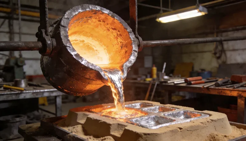
Aluminum casting is a process in which aluminum ingots or recycled scrap are melted and poured by gravity or injected under pressure into a mold cavity that defines the final part geometry. After solidification, the mold is opened or broken, and the casting is cleaned, trimmed, and often heat treated or machined to meet dimensional and surface requirements. Because the metal is shaped in liquid form, casting can yield near-net-shape parts that require relatively little subsequent material removal. The aluminum casting market is forecast to exceed 100 billion USD around 2025 and grow at roughly 5–8% CAGR into the early 2030s, reflecting rising demand from automotive, machinery, and aerospace sectors. This growth is supported by aluminum’s favorable strength‑to‑weight ratio, recyclability, and cost competitiveness versus alternative materials.
Key Advantages Over Other Manufacturing Methods
Aluminum casting allows highly complex geometries, thin walls, and integrated features such as ribs, bosses, and internal cavities that would be difficult or very expensive to achieve via machining from solid bar or plate. Compared with steel or iron castings, aluminum parts offer significantly lower weight while still providing good tensile strength, stiffness, and fatigue performance for many structural and housings applications. Casting can be more economical than CNC machining at medium‑to‑high volumes because it minimizes material waste and reduces cycle times per part once tooling is in place. Aluminum also offers good corrosion resistance, excellent thermal conductivity, and good electrical conductivity, which makes cast parts attractive for housings, heat sinks, and electric powertrain components. Finally, aluminum’s recyclability supports sustainability targets, an increasingly important purchasing criterion in automotive and industrial supply chains.
Common Applications by Industry
Automotive: Engine blocks, transmission housings, EV motor housings, inverter housings, wheels, structural nodes, and suspension components use high‑pressure die casting and permanent‑mold casting extensively.
Aerospace: Brackets, housings, and structural fittings benefit from A356 and similar alloys with high strength‑to‑weight ratio and good fatigue performance, often in sand or permanent‑mold cast form.
Industrial machinery: Pump bodies, valve bodies, gearbox housings, and machine frames use sand casting or gravity casting for larger, complex parts.
Electronics and telecom: Heat sinks, enclosures, and EMI‑shielded housings rely on die‑cast aluminum for thin walls and good surface finish.
Consumer products: Power tool housings, lighting fixtures, appliance parts, and furniture components take advantage of aluminum’s formability and attractive appearance after finishing.
Types of Aluminum Casting Methods
Die Casting (High Pressure)
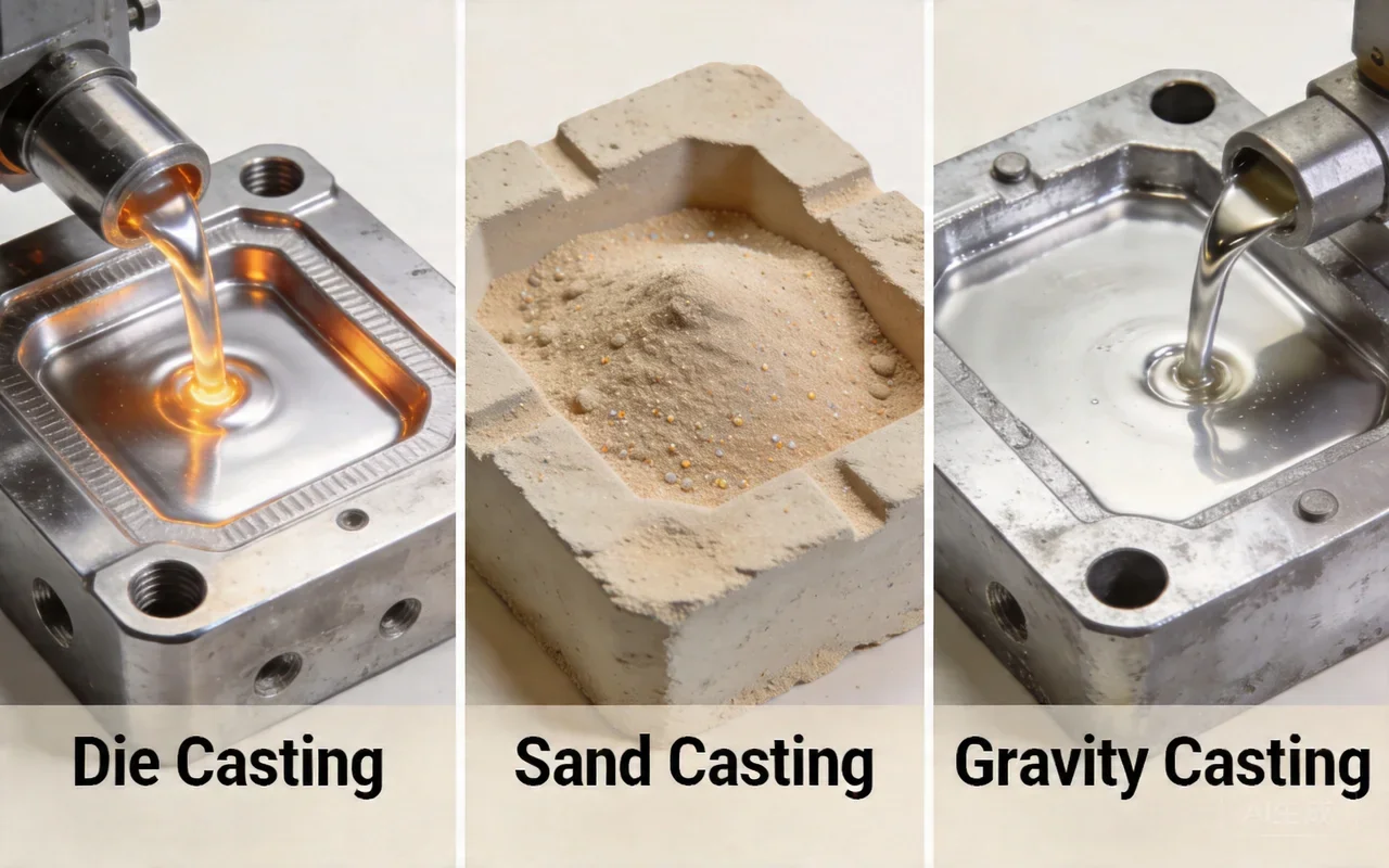
High‑pressure die casting (HPDC) injects molten aluminum into a hardened steel die at high velocity and pressures typically ranging from hundreds to over 1,000 bar. The steel dies are reusable and mounted on a die casting machine; molten metal is shot into the cavity, solidifies quickly, and the part is ejected, enabling very short cycle times. HPDC achieves excellent dimensional accuracy and smooth surface finish (often Ra around 1.6–3.2 µm) and is ideal for thin‑wall, complex parts in high volumes. However, tooling costs are high, and internal porosity from trapped gas limits the extent of heat treatment and welding compared with sand‑cast structural grades.
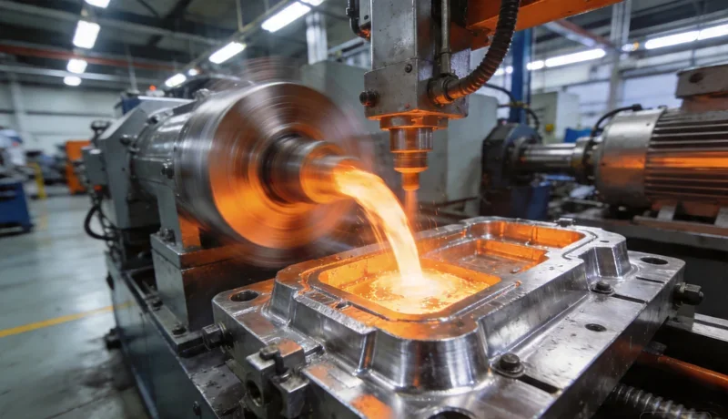
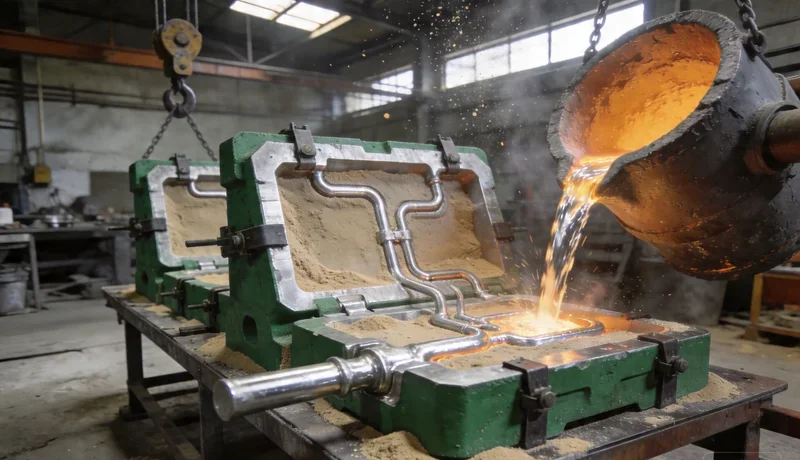
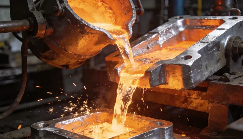
See learn about our high-pressure die casting services, Sand Casting, and Gravity Casting service pages. For a deeper die-casting focus, read the Aluminum Die Casting Guide.
Process comparison
| Attribute | Die casting (HPDC) | Sand casting | Gravity casting (permanent mold) |
|---|---|---|---|
| Process description | Molten aluminum injected into steel dies at high pressure using a die casting machine. | Molten aluminum poured by gravity into expendable sand molds packed around a pattern. | Molten aluminum poured by gravity into reusable metal molds, sometimes with low pressure assist. |
| Typical part size | Small to medium parts, up to medium‑large housings; weight often < 20–30 kg. | Very small to extremely large castings; from <1 kg to hundreds of kg. | Small to medium‑large parts; generally below sand casting’s maximum sizes. |
| Surface finish | Very good; smooth surfaces suitable for cosmetic parts with minimal finishing. | Rougher surfaces due to sand texture; often needs machining or shot blasting. | Better than sand, slightly rougher than HPDC; good for many visible components. |
| Dimensional accuracy | Tight tolerances, typically around ±0.10–0.25 mm on small features. | Looser tolerances, typically ±0.8–1.5 mm depending on size; CT8–CT11 grades. | Intermediate tolerances, typically ±0.25–0.50 mm. |
| Production volume suitability | Best for high‑volume production (thousands to millions of parts). | Best for low to medium volumes or large parts (tens to low thousands per year). | Ideal for medium volumes needing better properties than sand but lower tooling cost than HPDC. |
| Typical cycle time | Very short, often 30–120 seconds per shot depending on part size. | Longest; molds must be packed, poured, cooled, and broken; cycles often minutes to tens of minutes. | Moderate; reusable molds allow faster cycles than sand, often a few minutes per part. |
Sand Casting
Sand casting uses expendable sand molds formed around a pattern to create the cavity; molten aluminum is poured by gravity and allowed to solidify before the sand is broken away. This method accommodates very large parts and complex shapes with relatively low tooling cost, since patterns for sand molds are much cheaper and faster to produce than hardened steel dies. Surface finish is rougher (often Ra above 6.3–12.5 µm), and dimensional tolerances are looser, so more machining is typically required. Sand casting is best suited for low‑to‑medium production volumes or large, heavy components where die casting would be uneconomical.
Gravity Casting (Permanent Mold)
Gravity permanent‑mold casting (also called gravity die casting) pours molten aluminum into reusable metal molds under gravity, without the high injection pressures of HPDC. The metal mold provides better cooling control and surface finish than sand, yielding improved mechanical properties and dimensional repeatability. Tooling cost is higher than sand casting but lower than high‑pressure die casting, and cycle times are moderate, making it suitable for medium volumes. Permanent‑mold casting works well for wheels, suspension arms, and other components requiring better properties than sand castings but not the extreme volumes of HPDC.
The Aluminum Casting Process Step by Step
Melting and Alloy Preparation
Aluminum casting typically starts with charging furnaces (reverberatory, crucible, or electric) with primary ingots and returns (gates, runners, scrap), then melting to around 660–780 °C depending on alloy and process. ASM‑type guidelines often recommend superheating above the liquidus and then holding at controlled temperatures (commonly 680–730 °C) to balance fluidity and minimize oxidation and hydrogen pickup. Alloying additions (Mg, Cu, Si, etc.) are adjusted, and melt treatment steps such as degassing, fluxing, and grain refinement (e.g., Ti‑B master alloys) are applied to improve cleanliness and mechanical properties. Hydrogen degassing with inert gas or rotary degassers reduces porosity‑causing gas levels, a critical quality step for structural castings.
Mold Preparation and Tooling
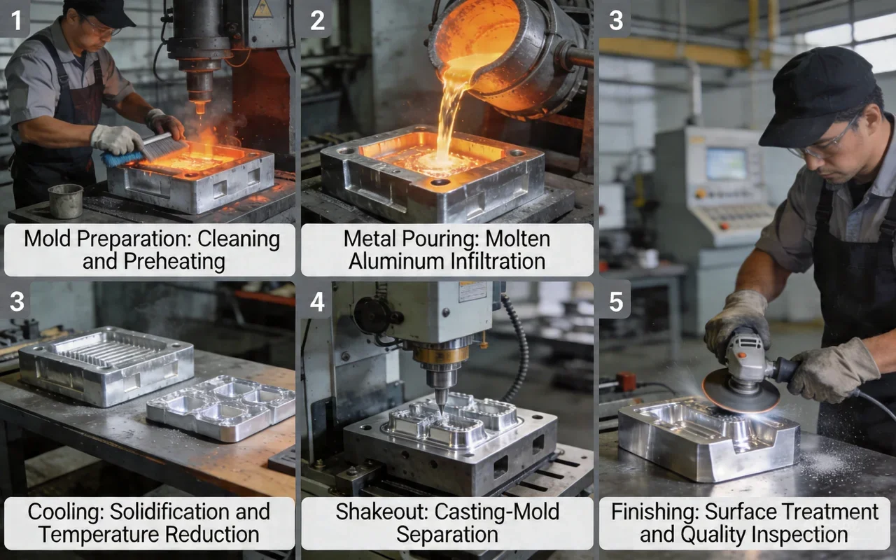
For sand casting, molds are prepared by compacting sand around a pattern, inserting cores for internal cavities, and applying mold coatings to control surface finish and metal penetration. In die casting and permanent‑mold casting, steel or iron molds are coated with refractory die lubricants, preheated to a specified temperature range, and mounted on machines for controlled filling. Proper venting, gating, and riser design, based on foundry guidelines and simulation, ensures directional solidification and minimizes turbulence, gas entrapment, and shrinkage defects. Tooling maintenance—polishing, repairing erosion, and checking cooling channels—is essential for dimensional consistency and surface quality over long production runs.
Pouring and Solidification
In sand and gravity casting, molten aluminum is poured by ladle into the gating system, with flow rates controlled to avoid turbulence and mold erosion. In HPDC, the metal is injected at high speed through shot sleeves and gates, filling the cavity in milliseconds to a few tenths of a second. Solidification is controlled by mold materials, cooling channels, and riser placement to encourage feeding of shrinkage from liquid reservoirs. Cooling rates in metal molds are higher than in sand, leading to finer microstructures and potentially higher strength in permanent‑mold and die cast parts.
Shakeout and Cleaning
Once solidified, sand castings undergo shakeout, where the sand mold is broken and removed mechanically or vibrationally. All processes require removal of gates, risers, and flash by sawing, grinding, or trimming presses, followed by shot blasting or other cleaning to remove scale and surface residues. Dimensional inspection at this stage can detect gross defects or misruns before more value‑adding steps are applied. Clean castings are then routed to machining, heat treatment, or finishing lines based on specifications.
Heat Treatment and Finishing
Many sand and permanent‑mold cast alloys such as A356 are heat treated (e.g., T6: solution treatment, quench, artificial aging) to significantly increase tensile strength and yield strength while maintaining reasonable elongation. HPDC alloys are often used in as‑cast or T5 conditions because higher porosity can cause blistering during solution treatment, though specialized processes exist for structural die castings. Finishing operations include CNC machining of critical features, surface treatments (anodizing, powder coating, painting), and impregnation for leak‑tightness in pressure‑containing parts. Final inspection verifies dimensions, surface quality, and mechanical properties before shipment.
Aluminum Casting Materials and Alloys
A356 — The Most Common Sand Casting Alloy
A356 is an Al‑Si‑Mg alloy with about 6.5–7.5% Si and 0.2–0.5% Mg, plus very low copper, giving good corrosion resistance and excellent response to T6 heat treatment. In T6, it provides high tensile and yield strength with relatively high elongation, making it a preferred option for structural and safety‑critical castings in automotive and aerospace applications. A356 is widely used for sand and permanent‑mold cast components such as wheels, suspension arms, and complex housings needing weldability and good fatigue performance. Its fluidity is lower than die‑casting alloys like ADC12, so casting design and feeding must be carefully engineered, especially for thin sections.
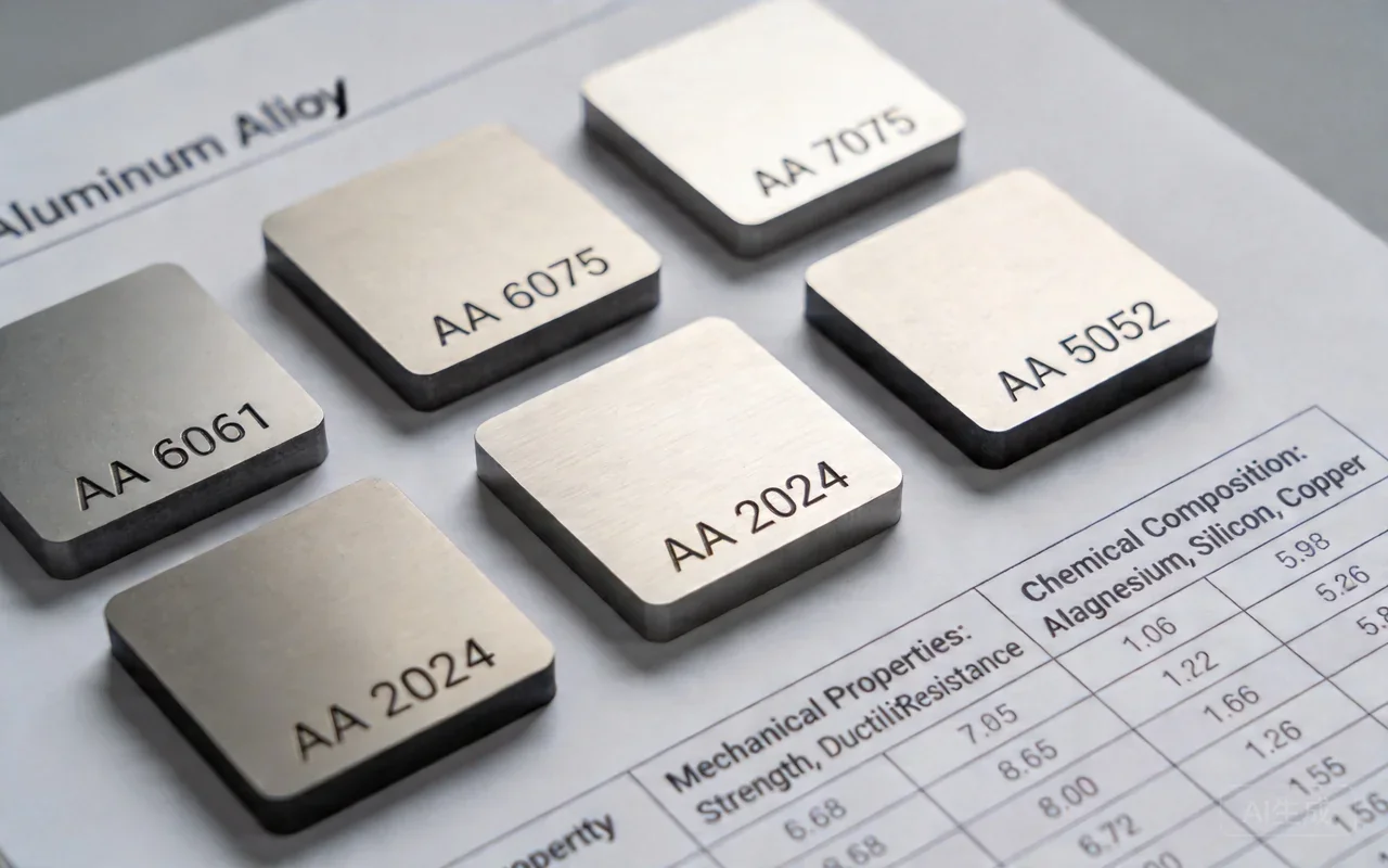
Alloy properties comparison
(Values are indicative ranges; exact properties depend on temper, casting process, and section thickness.)
| Alloy | Key chemistry highlight | Typical use / process | Relative tensile strength | Relative yield strength | Relative elongation / ductility | Corrosion resistance | Relative cost (material + processing) |
|---|---|---|---|---|---|---|---|
| A356 | Al‑Si‑Mg; 6.5–7.5% Si, low Cu. | Sand and permanent‑mold, often T6; structural parts. | High when T6 treated. | High when T6 treated. | High ductility vs die‑cast alloys. | Excellent in marine/outdoor use. | Medium; heat treatment adds cost. |
| ADC12 | Al‑Si‑Cu; ~9.6–12% Si, 1.5–3.5% Cu. | HPDC; thin‑wall, complex components. | High as‑cast strength. | Moderate‑high. | Lower than A356; moderate. | Moderate; less than A356. | Low‑medium per part at high volume. |
| A380 | Al‑Si‑Cu; 7.5–9.5% Si, 3–4% Cu. | HPDC; housings, brackets, general castings. | High as‑cast strength and hardness. | High. | Lower elongation; more brittle vs A356. | Lower due to higher Cu content. | Very cost‑effective for high volumes. |
| A383 | Al‑Si‑Cu variant similar to ADC12. | HPDC for complex thin‑walls with better ductility. | Moderate‑high. | Moderate. | Improved vs A380 in some cases. | Moderate. | Similar to ADC12. |
| LM25 | Al‑Si‑Mg similar to A356. | UK/EU sand & permanent‑mold; structural, marine. | High in heat‑treated tempers. | High. | High; good toughness. | Excellent, suited for marine use. | Medium; like A356. |
| 6061 (wrought) | Al‑Mg‑Si wrought alloy. | Typically extruded/forged, not a standard cast alloy. | Very high in T6 but as wrought. | Very high. | Good ductility. | Excellent corrosion resistance. | Higher cost; machining from solid or forging. |
ADC12 and A380 — High Pressure Die Casting Alloys
ADC12 (JIS) and A380 (ASTM/SAE) are Al‑Si‑Cu die casting alloys optimized for fluidity, castability, and as‑cast strength in high‑pressure die casting. A380 typically contains around 7.5–9.5% Si and 3–4% Cu, offering high tensile strength and hardness, but lower corrosion resistance compared with low‑copper alloys. ADC12 has slightly higher Si (9.6–12%) and moderate Cu (1.5–3.5%), providing excellent fluidity for thin‑wall, intricate parts and a good balance of strength and castability. These alloys are dominant in automotive and electronics housings, brackets, and complex small‑to‑medium structural components produced in very high volumes.
A383 — Improved Ductility Die Casting Alloy
A383 (also related to ADC12 in some standards) is an Al‑Si‑Cu die casting alloy formulated to improve ductility and reduce hot‑tearing risk relative to A380 in complex castings. It offers good fluidity and is often selected for thin‑section die castings that require somewhat better elongation or reduced cracking during ejection and cooling. While its corrosion resistance and strength are not as high as optimized sand‑cast structural alloys, A383 remains a practical choice for housings and brackets requiring improved filling of difficult geometries.
LM25 — UK/European Standard
LM25 (BS/EN designation) is broadly similar to A356, with Al‑Si‑Mg chemistry that allows good mechanical properties in heat‑treated tempers and strong corrosion resistance. It is widely used in the UK and Europe for sand and permanent‑mold castings in automotive, marine, and general engineering applications, especially where weldability and toughness are important. LM25 castings in heat‑treated condition can achieve high proof stress and tensile strength along with useful elongation, making them suitable for pressure‑tight components and safety‑critical structures.
Material Selection Guide by Application
Structural automotive / aerospace: A356 or LM25 in T6 for suspension arms, wheels, and structural brackets where strength, fatigue resistance, and weldability are critical.
High‑volume housings and brackets: A380 or ADC12 for engine covers, gear housings, motor housings, and consumer electronics shells produced by HPDC.
Very complex thin‑wall die castings: ADC12 or A383 where superior fluidity and reduced hot tearing are needed, often with moderate mechanical demands.
Corrosive or marine environments: A356/LM25 due to low copper content and better general corrosion resistance compared with Cu‑rich die casting alloys.
Common Aluminum Casting Defects, Causes and Solutions
Porosity and Gas Defects
Porosity in aluminum castings arises from gas entrapment (hydrogen, air) and shrinkage during solidification, often manifesting as internal voids or surface blowholes. Gas porosity is typically caused by hydrogen absorption in the melt, turbulence during pouring or injection, and inadequate venting in dies or molds. Prevention strategies include proper melt degassing, reducing turbulence with optimized gating, using vacuum‑assisted die casting, and maintaining clean, dry charge materials. NADCA and ASM guidelines emphasize monitoring melt quality and using appropriate die venting to keep porosity within acceptable levels.
Shrinkage Defects
Shrinkage defects occur when insufficient feed metal is available during solidification, leading to cavities or hot spots in thick sections and junctions. Poor riser design, non‑directional solidification, and abrupt section changes increase the risk of shrinkage porosity and macro‑shrinkage. Solutions include using properly sized and placed risers, chills, and tapered sections to encourage feeding toward risers, as well as employing simulation tools to optimize solidification patterns.
Cold Shuts and Misruns
Cold shuts and misruns appear as incomplete filling, laps, or seams where two metal fronts fail to fuse properly because of low temperature or slow flow. Causes include insufficient pouring temperature, long thin flow paths, poorly designed gates, or too slow injection speed in die casting. Corrective actions focus on increasing metal and mold temperatures within safe limits, improving gating layout, and adjusting injection parameters to ensure complete, hot filling.
Inclusions and Surface Defects
Inclusions are non‑metallic particles such as oxides, slag, or sand embedded in the casting, leading to reduced mechanical properties and cosmetic flaws. They typically stem from poor melt cleanliness, erosion of refractory linings, or sand breakdown in molds. Surface defects like roughness, scabs, and metal penetration often result from unsuitable sand properties, inadequate coatings, or die‑lubricant management. Prevention involves rigorous melt filtration, proper fluxing, controlling sand quality, using appropriate mold/die coatings, and maintaining gating systems to minimize turbulence.
Defect Prevention Checklist
- Control melt quality: regular hydrogen testing, degassing, and fluxing.
- Optimize gating, venting, and risers using simulation and NADCA/ASM guidance.
- Maintain stable mold and die temperatures and use proper coatings and lubricants.
- Standardize pouring and injection parameters to minimize turbulence and air entrapment.
- Implement robust inspection (X‑ray, pressure tests) to monitor defect trends and close feedback loops.
Quality Control and Certifications in Aluminum Casting
Industry Certifications and What They Mean
Professional aluminum foundries often operate under ISO 9001 quality management systems, providing documented process control, traceability, and continuous improvement. Automotive suppliers commonly require IATF 16949, which adds automotive‑specific controls on APQP, PPAP, and defect prevention. Environmental and material compliance with RoHS and REACH is increasingly demanded, restricting hazardous substances and ensuring safe chemical management in coatings, lubricants, and alloying additions. Many customers also reference NADCA standards for die casting practices and ASM handbooks for metallurgy and testing expectations.
Inspection Methods: X-ray, Pressure Testing, CMM
X‑ray / CT inspection: Used to detect internal porosity, cracks, and inclusions in safety‑critical castings.
Pressure and leak testing: Applied to housings, valves, and fluid components to verify leak‑tightness under specified pressures.
CMM and dimensional inspection: Coordinate measuring machines verify geometric tolerances and GD&T callouts against drawings.
Mechanical testing: Tensile tests, hardness, and impact testing confirm that heat‑treated castings meet specified properties.
Tolerance Standards for Cast Parts
Typical linear tolerances for aluminum castings vary by process, with HPDC often achieving around ±0.10–0.25 mm on small features, permanent‑mold around ±0.25–0.50 mm, and sand casting around ±0.8–1.5 mm depending on size. International standards such as ISO 8062 define casting tolerance grades (CT1–CT12), where CT6–CT8 are common for precision and general‑purpose castings. Additional standards like NADCA #207 provide specific tolerance tables and guidelines for aluminum die cast parts.
Aluminum Casting Cost Factors and Budgeting
Tooling and Mold Costs
Sand casting patterns: Typically the lowest tooling cost; simple patterns may be in the low thousands USD, with more complex coreboxes higher.
Permanent‑mold tools: Medium investment; often mid‑five to low‑six‑figure USD levels depending on size and complexity.
High‑pressure die casting dies: Highest tooling cost, typically tens of thousands to several hundred thousand USD for multi‑cavity automotive tools.
Per-Part Cost by Casting Method and Volume
Low volumes (tens to low hundreds per year): Sand casting is usually most economical because tooling is inexpensive, despite higher per‑piece labor and machining.
Medium volumes (hundreds to low tens of thousands): Gravity permanent‑mold can offer a good balance with moderate tooling and reasonable per‑part costs.
High volumes (tens of thousands to millions): HPDC has the lowest per‑part cost once tooling is amortized, especially for small‑to‑medium parts.
Secondary Operations and Their Impact
Secondary operations such as CNC machining, drilling, threading, and surface treatments (anodizing, powder coating, impregnation) can account for a significant share of part cost, especially for tight tolerances. Pressure‑tight parts may require machining sealing surfaces plus impregnation or leak testing, adding both cycle time and cost. Minimizing machining stock through good casting design can substantially reduce the overall project budget.
Cost Optimization Tips for Buyers
Match casting method to volume and size to balance tooling and per‑piece cost.
Design for casting to reduce machining and scrap (uniform walls, generous radii).
Standardize alloys and finishes to leverage foundry experience and minimize changeovers.
Use realistic tolerances; overly tight tolerances can drastically increase machining and inspection costs.
Design for Aluminum Casting (DFC) Principles
Draft Angles and Wall Thickness
Cast parts require draft angles on vertical faces to allow easy ejection from molds, with typical recommendations around 1–3 degrees for die castings and slightly higher for sand molds. Uniform wall thickness helps promote even solidification, reducing residual stresses and shrinkage porosity; sudden thickness changes should be avoided or transitioned gradually. NADCA and ASM design rules emphasize optimizing wall sections for both castability and mechanical performance.
Fillets, Radii and Corner Design
Sharp internal corners concentrate stress and hinder metal flow, so fillet radii are specified at ribs, bosses, and intersections to improve fatigue resistance and feeding. Generous radii at junctions also reduce hot spots that may lead to shrinkage cavities or cracking. External edges may also be slightly rounded to improve die life and reduce machining requirements.
Gate and Riser Design Considerations
Effective gating and riser systems ensure smooth metal flow, controlled filling, and proper feeding of shrinkage during solidification. For die casting, gate location and thickness govern flow patterns, air evacuation, and weld lines, which are addressed in NADCA design guidelines. For sand and permanent‑mold casting, risers must be sized and placed to remain liquid longer than the casting sections they feed, enabling directional solidification.
Aluminum Casting vs CNC Machining: When to Use Which
When to Combine Casting with CNC Machining
In many projects, casting is used to create the near‑net‑shape blank, and CNC machining then finishes critical surfaces, holes, and threads to tight tolerances. This hybrid approach leverages casting’s cost advantage for bulk geometry and machining’s precision for functional interfaces. It is common in automotive and industrial housings, where sealing faces, bearing bores, and alignment features are machined after casting. Combining both methods often provides the best balance of cost, performance, and lead time for medium‑to‑high‑volume applications.
| Factor | Aluminum casting | CNC machining from billet |
|---|---|---|
| Upfront cost | Tooling cost (pattern, mold, die) can be significant. | Minimal tooling; mostly fixturing and programming. |
| Per‑part cost | Low at medium/high volumes; efficient material use. | Higher due to machine time and material waste (chips). |
| Design complexity | Excellent for complex 3D shapes and internal cavities. | Limited for internal cavities; 5‑axis helps but raises cost. |
| Tolerances | Moderate; best with HPDC, tighter with post‑machining. | Very tight tolerances achievable directly. |
| Lead time | Longer initial lead time due to tooling design and build. | Faster to start, ideal for prototypes and small batches. |
| Material properties | Microstructure depends on cooling; may include porosity. | Wrought properties (e.g., 6061‑T6) often higher and more uniform. |
| Scrap and sustainability | Lower material waste; runners can be recycled. | Higher material removal and scrap volume. |
How to Choose the Right Aluminum Casting Method
For High Volume Production
For small to medium parts with complex geometries and thin walls at annual volumes in the tens of thousands or more, high‑pressure die casting is usually the preferred method. The high tooling cost is offset by very low per‑part cost, high productivity, and excellent surface finish and dimensional repeatability. Typical examples include automotive transmission housings, EV motor housings, and consumer electronics enclosures.
For Large and Complex Parts
For large components, low volumes, or very heavy castings, sand casting is often the only practical and economical choice. Examples include large pump bodies, industrial gearbox housings, and heavy machine bases where part size and geometry make die tooling prohibitively expensive. Sand casting is also favorable for early prototypes of large parts before committing to permanent tooling.
For Balanced Performance and Cost
When volumes are moderate and parts need better mechanical properties and surface finish than sand casting but cannot justify HPDC tooling, gravity permanent‑mold casting offers a good compromise. Typical applications include wheels, suspension arms, and medium‑sized housings where structural performance and aesthetics matter but volumes are not extremely high. Our cost reduction tips and foundry consultation can refine the choice based on tolerance requirements, alloy selection, and project budget.
Frequently Asked Questions
- What is the most common aluminum casting method for high-volume production?
- High‑pressure die casting is the most common method for high‑volume aluminum parts because it offers fast cycle times, tight tolerances, and low per‑part cost once tooling is in place.
- How much does aluminum casting tooling typically cost?
- Sand casting patterns may cost a few thousand USD, permanent‑mold tools can reach mid‑five to low‑six figures, and HPDC dies often range from tens of thousands to several hundred thousand USD depending on size and complexity.
- What is the difference between A356 and ADC12 aluminum?
- A356 is an Al‑Si‑Mg alloy with low copper, optimized for sand/permanent‑mold casting and heat treatment, offering high ductility and corrosion resistance. ADC12 is an Al‑Si‑Cu die casting alloy with higher silicon and copper, optimized for fluidity and as‑cast strength in HPDC but with lower ductility and corrosion resistance compared with A356.
- How do I choose between die casting and sand casting for my project?
- Choose die casting for high volumes, small‑to‑medium parts, and tight tolerances; choose sand casting for large parts, low volumes, or when you want low tooling cost and accept more machining. Consider expected quantity, size, tolerance needs, and budget when deciding.
- What tolerances can I expect from aluminum casting?
- Typical linear tolerances are about ±0.10–0.25 mm for HPDC, ±0.25–0.50 mm for permanent‑mold, and ±0.8–1.5 mm for sand casting depending on feature size and casting grade. Tighter tolerances are usually achieved by machining critical surfaces after casting.
- Is aluminum casting cheaper than CNC machining for large quantities?
- For large quantities, aluminum casting is usually cheaper per part because of reduced material waste and faster production once tooling is amortized. CNC machining remains more economical for prototypes and low volumes where tooling costs cannot be spread over many parts.
- What causes porosity in aluminum castings and how to prevent it?
- Porosity is mainly caused by gas absorption (especially hydrogen), turbulence during filling, and inadequate feeding during solidification. Prevention involves proper melt degassing, clean charge materials, optimized gating and venting, and, in die casting, possibly vacuum assistance.
- How long does the aluminum casting process take from design to delivery?
- For sand castings, lead time from design to first articles can be a few weeks, while permanent‑mold and die casting tools may require several weeks to a few months for design, build, and sampling. Production lead time then depends on volume and scheduling, but mature HPDC lines can produce thousands of parts per day.